"Some conservative branches of manufacturing, including moldmaking, demand a lot of hard evidence when it comes to gaining buy-in for new technologies such as additive manufacturing,” says Christoph Hauck, CEO of Germany-based company Toolcraft. “On the one hand, there are constraints and conditions a shop must comply with that can be a hindrance to an innovative solution. On the other hand, industry wants shops to implement up-to-date and innovative manufacturing technologies to go beyond the limits of what’s possible today.”
Founded in 1989, the medium-sized, family-owned company Toolcraft, with 390 employees, considers itself a pioneer in additive manufacturing (AM) and the design and manufacture of customized turnkey robotic solutions, as well as injection molding, CNC machining, EDM and moldmaking.
Featured Content
With the opening of its new metal laser melting center two years ago, Toolcraft laid the foundations for pushing the limits of conventional manufacturing. Five Trumpf TruPrint 3000, three Concept Laser machines (M2 Cusing, M1 Cusing and M2 Cusing Multilaser) and one EOS M290 machine are running in the company’s AM center, which is equipped with sensors to monitor temperature and humidity and an argon warning system. Constant overpressure and air exchange at the rate of six times per hour ensure that the air is free of powder. Toolcraft has invested about 12 million euros in this innovative technology center, including a vacuum furnace and a simulation-based software environment.
Realizing a Consistent Digital Process Chain
With Siemens NX, Toolcraft has realized a digital process chain that is consistent and traceable for all process steps, which is very important as the company not only produces tools and molds, but also manufactures aerospace parts. The complete additive process chain is Nadcap (WLD for AM) certified as well as the system for non-destructive testing (Nadcap NDT). “Introducing one software – Siemens NX – enabled us to get rid of isolated 3D printers and four different software packages with numerous interfaces and formats,” says Hauck.
While in the past, designers and engineers had to use several software systems to design, simulate and then postprocess and prepare the part for 3D printing, Siemens NX supports the full AM process-thread, using one data format for CAD/CAE/CAM and one user interface. According to Andreas Saar, additive manufacturing initiative leader at Siemens PLM, an uncontrolled workflow is the biggest barrier today to industrialize AM. In an uncontrolled workflow, design software, simulation software and print preparation software, through to the AM process, heat treatment, finishing, inspection and the end-use part form a disconnected process chain, where the various steps in the AM process are not automated and don't speak a common language.
“Multiple file conversions and an uncontrolled workflow do not ensure the traceability and reproducibility we need to industrialize 3D printing,” says Toolcraft engineer Ralf Domider, engineering and simulation metal laser melting. “The goal has to be the automation and digitalization of the entire end-to-end process,” he says.
Topology Optimization
Siemens NX also allows for topology optimization, which remains the most general and powerful tool for developing novel shapes and concept designs. Since the software allows for consistency and traceability of all process steps, the designer can implement changes on the topology-optimized part directly, saving the reverse-modelling step (more information provided below).
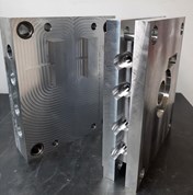
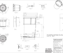
Toolcraft used topology optimization to redesign an existing injection mold for a camera cover in order to improve cooling and reduce weight. The result was a weight-optimized injection mold, designed to produce a part for a customer from the optical industry made of polycarbonate (see photo).
Topology optimization finds the best distribution of material for the given constraints
“The idea was to gain experience in the digital process chain, and as a beta user of Siemens’ NX software, including the Additive Manufacturing module, we decided to take a mold we used to manufacture conventionally with base plates, standard parts and insert and optimize the design for AM,” Domider explains. However, he adds, it is not as straight forward to redesign a mold using topology optimization as it might seem; while the software finds the most efficient design for 3D-printed parts, the designer has to consider various aspects if he wants to create a topology-optimized injection mold.
The Original Mold. The conventional injection mold for a camera cover made by Toolcraft measures 125 by 125 by 130 mm and consists of standard parts, a clamping plate, mold plate and mold insert including deep-bored cooling channels. The mold weighs around 50 kg and produces injection molded parts made of polycarbonate weighing 0.27 g.
Data Preparation. The first step is to purge, cleanse and analyze the existing CAD data of the original mold. This means that the designer has to delete most of the existing design parameters in order to re-think the existing conventional design. The designer needs to start from scratch, think additively without the existing constraints given by conventional machining techniques such as milling and EDM, Domider says. The next step is to define the build space (the envelope defining the allowable dimensional limits) available for the software to calculate an optimized design. Before the topology optimization process can start, the mold’s key features need to be defined, including guides, cooling channels, gating area, ejectors, etc.
Preliminary Considerations. When working with topology optimization, the designer does not work with standard control geometries such as plane areas, rectangles and circles anymore. The software generates the most optimum design in terms of weight, performance and cooling according to the given boundary conditions, given set of loads and constraints. Therefore, according to Domider, there are several important aspects and features which need to be considered before optimizing the design – which are often overlooked during the design process. Apart from defining areas which need to be plane (e.g. where the mold halves need to close), post-processing needs to be evaluated.
When a part leaves a 3D printer, it needs to be post processed on machining centers to mill or grind certain areas such as holes and threads to the required tolerances and surface qualities. Therefore, a designer has to plan for post processing and include fixtures and areas where the part can later be clamped with standard clamping tools on the machine or create special clamping devices which are printed in one process together with the mold. The whole manufacturing chain, including milling strategies for post processing needs to be efficient and economical.
Topology Optimization. Toolcraft looked at the mold’s existing design with the objective to minimize weight, optimize cooling while ensuring an injection pressure of 2500 bar and a clamping force of 150 kN. Topology optimization finds the best distribution of material given these goals and constraints. It works by taking a solid block of material in any shape and removes material from it to minimize or maximize an optimization objective like reducing weight, saving space or improving cooling. First, the data is prepared, i.e. the allowance is assigned, support structures are created and so on. The process is then simulated, and the data is sent directly to the machine.
Virtual Modeling. In contrast to some other software solutions, Siemens NX allows for a reversible process chain enabling fast changes. According to Domider, STL file format is simple and easy to output, but the problem with the STL format is that parametrics are lost, there is no solid body to work with anymore. STL files describe only the surface geometry of a three-dimensional object without any representation of color, texture or other common CAD model attributes. As a result, changes to the virtual model aren’t possible anymore, and the designer has to go back to his CAD software to re-design the part. Moreover, NC programming requires STP (Standard for the Exchange of Product Data) format, which is generated by the CAD software and can usually not be generated directly from the AM-specific software and files. Siemens NX has solved this problem and allows for consistency and traceability of all process steps, and the designer can implement changes on the topology-optimized part directly, saving the reverse-modeling step.
Simulation. To verify the design results, Toolcraft uses Simcenter Star-CCM+ to accurately predict real-world performance. The simulation tool captures all of the physics that will influence a part’s performance during its operational life. The computational fluid dynamics software allows to simulate how the mold interacts with fluids/liquids to reduce approximation and increase the accuracy of the design. This helps to optimize the cooling design (conformal cooling channels, optimized flow capacity, increasing cross-sectional areas). Simcenter also allows for FEM calculations and the prediction of distortion and shrinkage during the 3D- printing process and automatically compensates for these deviations.
The moldmaking industry has a long history and many processes are standardized. As a result, new approaches are viewed more critically, and the experience and acceptance of this new technology and way of thinking is limited at the moment.
The results indicate that the optimized mold made on a Truprint 3000 by Trumpf requires less manufacturing time, is smaller and 50 percent lighter than the original. Also, conformal cooling enables 30-percent faster cycle times and reduced energy consumption during injection molding. So, why have these topology optimized 3D-printed molds not been widely accepted in moldmaking yet?
“The moldmaking industry has a long history and many processes are standardized. As a result, new approaches are viewed more critically, and the experience and acceptance of this new technology and way of thinking is limited at the moment,” Domider says. “Moreover, there is a lack of long-term experience with additively made and topology-optimized molds. We have tested our molds on our injection molding machine with 2000 shots, but we cannot guarantee our customers 10,000 or more shots based on long-term experience.
Moldmakers are used to working with standard parts and design their molds in a way that’s tried and tested. To be honest, these special weight-optimized tools are not always needed in industrial applications, as the advantages very often don’t outweigh the extra cost, technology and expertise needed to create these molds. But here at Toolcraft, we will keep working on these future molds and keep working with additively designed mold inserts and conformal coolings for our customers to get the technology established in our industry.”
For More Information
Toolcraft, Inc. / 828-659-7379 / toolcraftinc.com
Siemens PLM Software / 1-800-498-5351 / plm.automation.siemens.com
RELATED CONTENT
-
From CAM, Cutters and Cooling to Corrosion, Cleaning and Control
A review of the year’s top tips on technologies and strategies to improve moldmaking operations from design to first shot.
-
3D Printing Enables Better Coolant Delivery in Milling Operations
Just like 3D printing enabled conformal cooling channels in molds, additive manufacturing is now being used to optimize coolant delivery in cutting tools.
-
Welcome to the Hub of Moldmaking in Portugal
Despite being a relatively small economy, the world's eighth-largest moldmaking country sits on the edge of Europe in relative obscurity. Evolved from a centuries-old glass-making tradition, Portugal today boasts some of the most advanced and innovative moldmaking businesses that have nearly doubled their export and production rate over the past ten years. Here is a look at this country’s recipe for success.




.JPG;width=550;quality=60)
.JPG;width=860)
.png;width=860)
.jpg;width=860)
.jpg;width=860)
