Metal AM Advances in Composite Tooling
Multiple metal additive technologies are gaining market acceptance and interest for composite tooling used in processes ranging from short-fiber injection to autoclave-cure prepreg.
#3dprinting
A recent development project evaluated the feasibility of using wire-arc additive manufacturing (WAAM) to produce layup tooling for complex contoured winglets mounted at the tips of the wings of MQ-9B SkyGuardian and SeaGuardian (shown above) remotely piloted aircraft from General Atomics Aeronautical Systems Inc. The additive tooling matched identical carbon fiber-reinforced composite tooling in terms of dimensional control, vacuum integrity and true position hole location, while providing improved durability. It also reduced maintenance costs, tool costs (30-40%) and tooling lead times (20-30%). Photo Credit: General Atomics Aeronautical Systems Inc.
Tooling is a vital element of any successful manufacturing program for composite parts, but it is often one of the last aspects considered during the development process. This is unfortunate since tool production — especially hard/metal tools — can have long lead times and add considerable cost to the bottom line. In fact, on many programs, tool production is the rate-limiting step, slowing commercialization and adding a high cost burden.
Luckily, metal additive manufacturing (AM) — which was initially used to produce prototype and low-volume metal parts — is starting to gain converts as a method to fabricate tooling components and entire molds. Like other 3D printing technologies, AM offers higher design freedom than machining or forming metals, plastics or composites themselves, easily printing geometries that are impossible or extremely costly to achieve with conventional manufacturing technologies. And most 3D printing processes can produce these structures with significantly shorter lead times, helping OEMs bring products to market faster, at lower cost and with a smaller carbon footprint.
Featured Content
In this article, we’ll cover several metal additive technologies and describe the types of tools or tool components they’re being used to produce and why. Here, we’re distinguishing between technologies that are already proven and are gaining wider acceptance on production programs — often for high-volume manufacturing — and technologies that are close to or just beginning use on commercial programs. In future articles, we’ll continue this discussion with additional technologies and describe novel ways that metal AM is helping toolmakers and molders produce better parts.
Production proven: Direct metal laser sintering/solidification
There are several metal AM technologies that are already production proven. That is, their processes have been vetted, their benefits catalogued and they currently are used to manufacture numerous components for injection molds producing parts for medium- and high-volume commercial programs in the automotive, rail, large appliance and personal care/medical industries.
Our focus is on one of these processes, generically called powder bed fusion (PBF), although variations include selective laser melting (SLM), selective laser sintering (SLS), electron beam melting (EBM) and direct metal laser sintering/solidification (DMLS).
In powder bed processes, a build plate sits in the bottom of a preheated chamber that is blanketed with inert gas at near-vacuum conditions. A very fine layer of metal powder is applied to the build plate via roller or blade, after which a thermal energy source (typically laser or electron beam) is directed at specific locations on the build plate where it melts and fuses powder into solid metal, forming the first layer of a part. The process continues until sufficient layers are deposited and fused to complete part geometry, after which it is removed from the chamber, depowdered and CNC machined to achieve required dimensions and finishes.
Benefits of powder bed processes include access to a broad range of metals and production of fully dense parts (without the need to sinter) with excellent mechanical properties (often as good as/or better than forged metal parts). It’s typical of AM/3D printing processes to offer greater design freedom than can be achieved — especially cost effectively — with conventional methods like machining, stamping, forging, casting or even molding because parts are built a single layer at a time in three dimensions. Proponents of the technology like to say that “complexity is essentially free in AM.”
Since powdered metal is laid down one layer at a time in the PBF process, sparse, solid or hollow lattice-type structures can be printed to reduce mass and material use in the same volume. It also can create complex internal geometry that is difficult or impossible to produce any other way. Because of this, very complex, hollow conformal cooling (or heating) channels that follow the contour of a part can be printed in geometries that would be impossible to gundrill.
For thermoplastics, this means cooling lines can be placed closer to critical geometry, allowing molders to shorten cycle times while reducing warpage, scrap and energy use. Similarly, for thermosets, heating lines can be created to speed curing times. PBF also permits creation of contiguous micro-scale holes/channels, producing selectively porous internal geometry that can be used very effectively for venting. This eliminates nearly all of the problems associated with porous metal-matrix composites (MMCs) that have long been used to create vented inserts for injection molds.
Limits of PBF include slow deposition rates, especially when intricate geometries are involved, high energy use and safety issues regarding the handling of fine powders, which require printers to be housed in specialized rooms (often temperature- and humidity-controlled cleanrooms with antistatic flooring staffed by operators wearing protective clothing). Some processes also induce high internal stresses in the workpiece that have to be post-print stress relieved.
Although build envelopes have been steadily increasing, they still are measured in millimeters or centimeters, not meters, so printable part sizes are necessarily small relative to other additive processes we’ll cover. Therefore, while PBF can produce extremely complex parts, the process is typically used to produce lifters, slides or inserts installed inside injection or compression molds rather than the molds themselves.
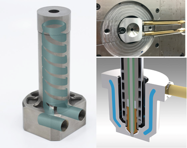
For injection molds, PCS Co. offers sprue bushings (left standalone and top right seated in tool) printed in H13 steel and gate inserts (bottom right) printed in 420 stainless steel that feature integral conformal cooling channels. Molders and moldmakers who’ve used the drop-in replacement report significant cycle time reductions. Photo Credit: PCS Co.
One mold component supplier that uses metal AM is PCS Co. (Fraser, Mich., U.S.), which rolled out its first H13 steel sprue bushings with conformal cooling channels for molds with cold runners at NPE 2018 and, two years later, added 420 stainless steel conformally cooled gate inserts for molds with hot runners. These PBF-printed, conformally cooled components are ideal for situations where large sprues feed small or thin parts. Since cooling represents 70-80% of the total injection cycle, moldmakers and molders using these drop-in replacements versus comparable components without conformal cooling have reported dramatic improvements in productivity — 15-80% cycle time reductions, depending on application. Given that molders are under constant pressure to reduce costs, PCS reports components can pay for themselves within days to weeks.
In one case, an automotive processor was injection molding spoiler seals in a two-cavity tool with a single cold runner that was 4-times thicker than the parts being produced, limiting the molder’s ability to reduce cycle times without risking stringing of still-hot material as the tool opened. After the original cold sprue bushing was replaced with a conformally cooled sprue bushing, cycle times were lowered, reducing cost pressures on the molder.
In another case, an automotive molder struggling to achieve a high-quality finish on a fastener in a four-cavity tool was maxing out injection pressures (155 MPa), risking over-shearing the material (with commensurate risk of property degradation) and damaging the press. After switching to a conformally cooled gate insert, cycle times were reduced from 20.3 to 17.8 seconds, injection pressures were reduced to 21 MPa and the processor saved $35,000-$40,000/month.
“Thanks to the versatility of 3D printing, we can manufacture complex parts with geometries that are practically impossible to make through conventional methods,” explains Paul Graceffa, PCS Midwest sales manager. “Customers ask us for 3D-printed technology for their molds because they know it gives them an edge over their competition. Most select these components because of the savings potential they offer during production of plastic [neat, reinforced and filled polymer] parts.”
Toolmakers, particularly those that also mold, are embracing the benefits of metal AM as well. Linear AMS, a Shapeways company (Livonia, Mich., U.S.), has used multiple metal AM technologies to produce conformally cooled inserts for its injection molds since 2005. Early on, Linear found itself owning one of only two DMLS printers in North America, so it quickly had aerospace and defense companies asking to visit and watch the printer work, since the only other DMLS printer was owned by an aerospace competitor. Soon, the Linear team became so skilled at designing and producing conformally cooled inserts that it effectively offshored its conventional moldmaking and focused on designing and producing conformally cooled inserts for its own molds and those of other toolmakers.
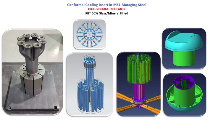
A good example of the type of complexity that Linear regularly produces with its conformally cooled inserts is the mold for a high-voltage electrical insulator used by the New York Transit Authority on railways for switching tracks. Reminiscent of a giant mushroom, the 123-millimeter-diameter x 270-millimeter-tall part is injection molded using 60 grams of 60% fiberglass/mineral-reinforced polybutylene terephthalate (PBT). The conformally cooled insert takes up nearly the entire core geometry of the single-cavity, oil-cooled tool, which was designed to produce three different insulators in three different lengths, which are selected by changing inserts. Given the size and length of the part, and the critical need to control dimensionality in the semi-crystalline polymer, the team wanted to better manage the temperature delta predicted by moldfilling analyses between the top and bottom/thick and thin sections of the part to achieve acceptable cycle times and extend the life of the mold. The insert nearly exceeded the height (Z-axis print envelope) of the DMLS printer. Linear is also molding the parts at its Charlotte, Mich., U.S. facility.
Intricate conformal cooling lines (three middle images) were printed in the tool insert (left) used to mold the highly reinforced thermoplastic polyester railway insulator (two images on far right). The DMLS-printed insert (produced in MS1 maraging steel) is shown on its build plate (left), from which it was wire EDM’d prior to final machining and installation in the mold. Photo Credit: Linear AMS, a Shapeways company.
“Over the years, we’ve heard so many positive comments from customers about the savings they’ve achieved by incorporating conformal cooling in their molds,” recalls David Myers, Linear AMS business development manager. “Among my favorites are: ‘We’ve never been able to process that detail prior to having the thermal control conformal cooling provides us,’ … ‘The reduced cycle is so significant that we’ve relaxed our CAPEX [capital expenditure] request to buy another injection molding machine,’ … and ‘We normally would have commissioned two tools [for this program] owing to capacity concerns, but we’re staying so far ahead with conformal cooling, that one tool is all we need.’”
Production ready: Wire-arc AM
Just as with polymer AM, the metal AM segment has responded to industry demand to be able to print much larger pieces much faster — albeit with less detail and using different technical approaches — by developing large-format AM (LFAM) printers. Metal LFAM is gaining converts — especially in the aerospace/defense industry — for single-sided prototype and production tooling. One such technology is wire-arc additive manufacturing (WAAM), a subset of the broader directed energy deposition (DED) category of 3D metal printing. Several companies sell WAAM systems; one that offers 3D metal printing services is Lincoln Electric Co. (Cleveland, Ohio, U.S.), which also offers post-print machining, fabrication and inspection.
WAAM combines a gas/metal arc welding source mounted to an industrial robot arm, a multiaxial positioner on which the build takes place, and metal in wire form, which is more economical than powder forms for the same alloys. The technology offers rapid deposition rates of 2.3-4.5 kilograms/hour and printing is done in open air without the need for protective enclosures or nitrogen blanketing. This greatly extends the build envelope — currently 1.2 x 1.5 x 2.0 meters in Lincoln’s metal 3D printing factory. The company says the technology can be readily scaled to even bigger systems, although Lincoln also has successfully printed multiple shorter tool segments and welded them together to produce a 3.1-meter-long x 3.8-meter-wide x 1.1-meter-tall tool. Printing and joining segments not only extends the effective “reach” of the technology but shortens build times too.
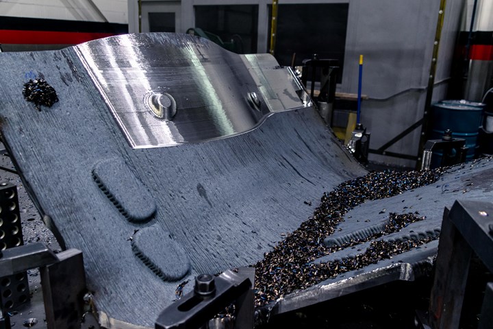
Since WAAM, like other LFAM processes, produces parts with bumpy/striated surfaces, post-print CNC machining is needed to achieve final part dimensions and an acceptable finish. In the image above, the as-printed mild steel surface is dark gray, while the post-print machined surface is silver. Photo Credit: Lincoln Electric Co.
As with other polymer and metal LFAM technologies, post-print machining is usually required because as-printed surfaces are too rough. Therefore, prints are slightly oversized to enable light CNC machining to achieve final dimensions and acceptable finishes.
WAAM produces fully dense parts without the need for post-print sintering or hot isostatic pressing (HIP). However, like other welding-type metal 3D-printing technologies, WAAM induces internal stresses that often, although not always, need to be addressed through thermal stress relief. Lincoln says geometry dictates whether this is done between printing and rough machining or between rough and finish machining. Still, compared to conventional metalworking techniques, WAAM can reduce tool lead times from months to weeks, helping manufacturers bring products to market faster.
And like other AM technologies, it increases design freedom and offers parts consolidation opportunities. For example, in the same build, WAAM permits conformal cooling/heating channels to be printed and/or integral backing structures that support thin-shell facesheets. Reduced tool mass makes shipping, handling and storage easier, plus, with less mass to heat/cool, autoclave cycles can be shortened.
For aerospace tooling, mild steels are favored when molding fiberglass-reinforced prepreg, while Invar is favored for carbon fiber-reinforced prepreg, owing to the desire to match tool and part coefficients of thermal expansion (CTE) to avoid breaking parts during demolding, or creating die-lock/trap conditions in overhang areas. WAAM is best suited for low-volume production of large structures measured in meters and hundreds of kilograms with complex geometries that would be challenging to achieve conventionally.
A good example is a tool designed, printed and tested during a development project between General Atomics Aeronautical Systems Inc. (GA-ASI, Poway, Calif., U.S.), a global company in unmanned aircraft systems (UAS), and Lincoln Electric.
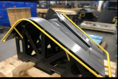
The severe curvature of this winglet’s facesheet is difficult and costly to achieve in conventional metal forming or machining, as well as in carbon fiber-reinforced composite tooling, adding cost and lead time to aerostructure programs, which is why GA-ASI has been evaluating LFAM options. While the backing structure for the WAAM tool could have been printed, GA-ASI determined it was faster and cheaper to produce and assemble it via conventional means. Photo Credit: General Atomics Aeronautical Systems Inc.
“We’ve developed an additive manufacturing ecosystem around DED technologies over the last few years after looking at several available large-scale metal deposition modalities for lamination tooling applications,” explains Steve Fournier, GA-ASI senior manager – Additive Design & Manufacturing Center of Excellence. “We sought a technology that allowed us to deposit metal as fast as possible while producing dimensionally precise features repeatedly in a vacuum-tight option capable of withstanding repeated autoclave cycles up to 350°F [177°C]. Among its potential uses, we’re especially interested in exploring steel and Invar lamination tools because of the cost and lead time challenges we routinely face with traditionally produced similar tools.”
The part selected for the study was an L-shaped, 2.7- x 1.4-meter fiberglass-reinforced epoxy prepreg winglet, which is mounted at the tip of each 12-meter wing on the MQ-9B SkyGuardian/SeaGuardian remotely piloted aircraft (RPA), which is used for activities like search and rescue, law and border enforcement and aerial surveillance, yet is compliant with civil airspace requirements. The winglets greatly reduce vortex-induced turbulence and drag generated at wing tips, helping the RPA fly for up to 40 hours while carrying a payload of up to 2,155 kilograms.
The winglet tool was a good test case owing to its size and severe curvature in several axes, which made it challenging to produce conventionally either in metal or carbon fiber-reinforced composites. The tool also features a return flange with compound curves that is mechanically fastened to the tool body to control joint dimensions during layup and cure, but is removed prior to demolding to facilitate part removal.
Once printed, machined to tolerance, assembled and inspected by Lincoln, GA-ASI put the tool through its paces. In addition to visual inspection and geometric dimensioning and tolerancing (GD&T) inspection via laser scanning, the team looked at moisture pickup on the material, CTE characteristics, tool release, porosity and vacuum integrity, and thermal behavior. Next, GA-ASI subjected it to durability/thermal cycle testing. This involved a large number of iterative cycles running the tool through the autoclave alone, laying up and curing a winglet composite part, then inspecting both tool and part.

Table 1: The first winglet tool produced in the study passed GA-ASI’s initial assessments. It was vacuum tight, had a uniform thermal survey and met/exceeded all target GD&T requirements. Data provided by General Atomics Aeronautical Systems Inc.
Although the tool is still completing qualification, it has so far demonstrated preliminary success in reaching production-level use for GA-ASI’s manufacturing operations. Furthermore, the company reports cost savings on the order of 30-40% and lead time savings of 20-30% versus conventional manufacturing.
“We’re expanding our use of DED tooling for production-level applications across multiple UAS platforms and we feel that DED is absolutely part of our tooling solution portfolio,” adds Fournier. “However, it’s important to understand that not all DED tools present the same cost benefits, so you have to find the right tool — those with challenging facesheet geometries with features like large curvatures that are difficult to form or weld conventionally — to build a good business case. Our industry would really benefit from strengthening its DED tool manufacturing supply chain.”
“It’s important to stress that our two companies did a lot of upfront work to determine the best design and manufacturing approaches for the winglet tool to minimize manufacturing costs,” adds Mike Wangelin, Lincoln Electric Additive Solutions business development manager. “As Steve notes, not every tool brings the same cost benefit. You definitely have to balance size and complexity against the difficulty of machining that shape out of a billet or forming it out of plate stock — especially these days with all the supply chain issues and cost increases on just about everything.”
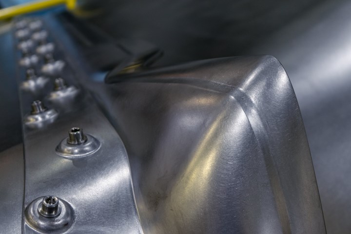
An interesting feature on the WAAM winglet tool is a removable return flange with compound curves that is mechanically attached to the tool body during layup and autoclave cure to control joint dimensions but is removed prior to demolding to assist with part removal. Produced as a separate print without need for a support structure, the flange, like the tool body itself, featured 9.5 millimeters of overbuild material for machine stock. The main body and flange were match drilled to control dimensional accuracy. Photo Credit: Lincoln Electric Co.
Production ready: Additive friction stir deposition
Another large-format metal AM process that is being evaluated in several industries was developed by Aeroprobe Corp. and spun off as a wholly owned subsidiary in 2018 as Meld Manufacturing Corp. (Christiansburg, Va., U.S.).
The multi-patented technology is generically described as additive friction stir deposition (AFSD), although Meld says it isn’t based on friction stir welding as the name seems to suggest. Still, both are solid-state joining processes and both rely on heat, pressure and shear generated by friction between a rotating tool and a workpiece to soften and bond two metals.
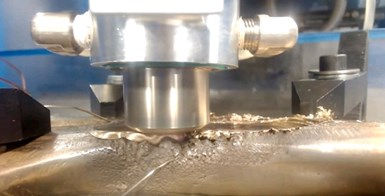
AFSD plastically deforms 1-2 millimeters (a value that is adjustable) of both the workpiece and the material being added and “stirs” them together, creating an isotropic, monolithic structure with select properties better than and grain structures finer than the parent materials. Unlike welding- or melt-based printing processes, it doesn’t induce high internal stresses in the workpiece. As a result, the process can do many interesting things.
Not only can it be used to additively manufacture parts and tools, but it also can coat, join and repair nearly any metal or MMC — even alloys like 7075 aluminum, which can’t be melt processed, 6061 aluminum, which can’t be printed with any other process and AZ91 magnesium, which can’t be fusion welded. It can repair valuable parts that can’t otherwise be fixed because welding would distort them. AFSD is essentially metal agnostic. It also can be used to create novel alloys that would be difficult to combine in conventional alloying processes. The main constraint is that both materials must have relatively similar melt temperatures and CTEs. The input material for Meld’s printers is bar stock, although powder feeders can be added. However, unlike PBF-type processes, it doesn’t require micron-scale powders or protective enclosures.
The AFSD process can apply coatings on other metals or repair high-value metal parts that otherwise can’t be welded conventionally. Here, it’s being used to repair corrosion/pitting on a nickel/aluminum/bronze (NAB) propellor blade. Photo Credit: Meld Manufacturing Corp.
Another interesting feature is AFSD’s rapid deposition rates. To date, rates as high as 13.6 kilograms/hour for aluminum; 4.9 kilograms/hour for steel; 7 kilograms/hour for titanium; and 0.7 kilograms/hour for nickel have been demonstrated. Aeroprobe and Meld CEO Nanci Hardwick says the deposition rate differences are more a function of which materials the company has spent the most time working with, rather than something inherent to the metals themselves. These high deposition rates are of interest to many aerospace, naval and defense companies that have been hard hit by supply chain disruptions, which have delayed critical forgings and castings. With AFSD, it may be faster to print a part than wait for it to be cast or forged and shipped.
Still another feature that makes AFSD interesting is that the process requires less energy and operates at lower temperatures than other metal AM printing processes and it does so in an open atmosphere — no vacuum, no nitrogen blanketing, no protective enclosure — which means its build envelope is only limited by the height of the pedestal or the size of the gantry on which the machine head is mounted. While Meld offers four standard printer sizes, it builds custom-size units as well. In fact, the company recently won a U.S. Army competition to build the world’s largest metal additive printer capable of producing a part that is 6.1 x 9.1 x 3.7 meters — large enough to print a mold or sections of a mold.
“If anyone is interested in bringing tool production in-house, it’s extremely easy to do with our machine and process,” adds Hardwick. “Our printer basically functions like a CNC machine except it puts metal back on a part rather than removing it. The printer runs on G-code and looks a lot like a mill. It’s a very approachable process that doesn’t require hazmat suits, special labs and a tech with a Ph.D. to run the equipment.”
AFSD produces near-net-shape parts that are fully dense and, unlike welding-based processes, it doesn’t induce high stresses in the workpiece that need to be post-print stress relieved. The company says it can go straight from printing to machining. Like other LFAM processes, it produces a bumpy/striated surface that needs to be cleaned up with CNC machining to create desirable finishes. Machine shops report that AFSD-printed parts machine the same as the parent material. Interestingly, not only does it not induce high stresses, but AFSD also changes the starting material’s grain structure.
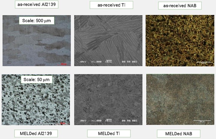
Metal parts from Meld’s AFSD process typically demonstrate grain sizes 1-2 orders of magnitude smaller and more isotropic than the parent material, which leads to parts with higher strength, and better corrosion and wear resistance than the starting material. Photo Credit: Meld Manufacturing Corp.
Meld already has machines in the field at universities and research centers in several countries as well as in companies in the aerospace, defense and marine markets. Most groups are using them for repair work or to print metallic parts, although interest in tooling is starting to grow. In fact, Hardwick reports that Meld has received inquiries about using AFSD to print tooling and then add a harder surface coating for applications with very high production rates, like automotive.
“It’s important to note that the Meld process is best suited for quickly producing big parts with fairly basic geometries,” adds Hardwick. “Fine detail is best achieved during finish machining rather than printing.”
One interesting tooling study that Meld has participated in with researchers at University of Dayton Research Institute (UDRI, Dayton, Ohio, U.S.) involved a large, printed 6061 aluminum mold used to autoclave cure a fiberglass-reinforced laminate part.
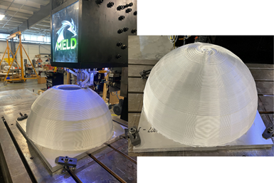
On the left is a 61-centimeter-tall hemisphere with a 61-centimeter-diameter base and wall thickness of 3.8 centimeters being printed in 6061 aluminum alloy — a material that cannot be printed in any other metal additive process. On the right is the completed part prior to CNC machining. Photo Credit: Meld Manufacturing Corp.
“The Meld process was selected because the size and depth of the tooling cavity would have required an unacceptable amount of machining time if done conventionally,” recalls Scott Huelskamp, P.E., UDRI senior composites engineer, team lead – advanced manufacturing process development, Structural Materials Division. “The Meld tool required only a final CNC machining pass after printing and gave us a tool that — aside from its initial bumpy surfaces — was otherwise nearly indistinguishable from one that had been machined from a billet of aluminum. To date, we’ve molded two parts on that tool and haven’t seen any porosity issues or undue movement in the tool.”
Article republished from sister publication CompositesWorld
RELATED CONTENT
-
Guidelines for Advanced Hot Runner Manifold Channel Design
Recent simulation research highlights the difference between a drilled, straight manifold channel design and a curved channel design produced via additive manufacturing.
-
Here Are Your Top 10 Most-Read Features of 2021
A list of the most-viewed features in MoldMaking Technology from January to November 2021.
-
How to Improve Mold Venting with Metal Additive Manufacturing
Patented 3D-printed mold insert design rapidly evacuates gases while preventing plastic flash-through, eliminates costly maintenance and need for press-side temperature-control units.


