Choosing CAD Software For 3D Mold Design
The world of CAD offers many alternatives to shops that want to use the latest 3-D technology for their mold design. This article looks at the benefits of the various approaches and offers some tips on choosing the most appropriate one.
#basics #FAQ
The main methods for creating designs are solid modeling and surface modeling. Surface modeling was the earliest form of CAD. It is based on shaping surfaces by pulling, bending, twisting and stretching them until the required shape is created. The surfaces can be joined together to enclose a volume and so represent complete objects. Solid modeling is based principally on standard geometric shapes, which can be combined in various ways, mainly developed from the Boolean operations of subtraction, addition and intersection. When they were first introduced almost 20 years ago, solid modelers had the advantage of being much easier to learn and use, but they lacked the flexibility of surface modelers in creating complex shapes. Since then, the developers of surface modelers have made their systems much easier to use, while the suppliers of solid modelers have added more flexible modeling tools. Thus, the distinction between the two types of system is now not so clear-cut.
Core and Cavity Design
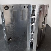
Surface modelers still have two general advantages over solid modelers for the first stage of the mold design, the creation of the core and cavity. First, they tend to be more tolerant of poor quality data. Both types of programs offer methods for fixing problems—such as poorly trimmed surfaces or overlapping edges—that might result from inexperienced product designers or inaccurate data translation. However, surface modelers can usually import data that a solid modeler might fail to accept at all.
Featured Content
Many surface and solid modeling programs offer wizards that can automate the creation of the core and cavity design from the part geometry. In both cases, the wizards allow the process to be completed more quickly. However, surface modelers are more flexible when the split surface generated by the automated method needs small adjustments to give the optimal design. In general terms, solid modeling can be better for simpler product designs because it remains easier to use, while the greater flexibility of surface modeling will be better for producing tooling from more complex components.
The other key choice for the tooling designer is whether or not to import the design history with the product model. This history shows how the design was created and maintains relationships between different elements of the design. Supporters of an integrated-software approach to product design and mold design claim that this is important as it allows changes to the product design to be reflected automatically in the mold design. However, retaining the history can be a disadvantage when making minor changes to the product design to aid manufacturability.
For example, the mold designer might want to increase the radius of one fillet in the model to improve material flow, but find that this is impossible without altering other linked fillets. Similarly, he may wish to increase the draft angle on a single surface to make it easier to remove the part from the mold and discover that this cannot be done without affecting other surfaces.
Mold Assembly
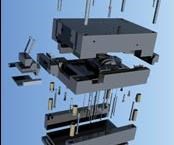
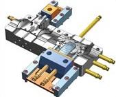
Once the core and cavity have been finalized, work can begin on the remainder of the mold assembly. Since most mold components are made up from fairly simple, prismatic geometry, solid modeling is the most appropriate method for their design and their assembly into the overall mold. Catalogs of standard mold components are required to complete the mold design efficiently as the user does not want to spend time creating these components over and over again. These catalogs are now available in a number of mold design systems, although the range of catalogs varies between the different systems. The software also needs to allow the moldmaker to design—quickly and easily—any non-standard components that might be required since few molds can be completed simply from standard components. Once completed, the designs can be added to the user’s personal catalog for future use.
As well as offering different catalogs, mold design systems differ in the degree of automation they incorporate. Some software includes a special option that allows parametric components to react automatically as they are placed within an assembly, adding all of the necessary fit-features to the connecting components. The software even adds the tolerances needed between the components.
For example, if the designer adds an ejector pin to the mold assembly, the software will automatically create the corresponding hole features in the plates through which it passes. Then the tolerances between the various components also are defined automatically. Thus, a sealing-fit hole is placed in the die block and the necessary clearance allowance added to the holes in all the other plates through which the pin passes. This automatic creation of relationships makes the development of the overall design much quicker than other 3-D mold design systems and also makes errors in the design process far less likely.
Of course, this software option maintains relationships in a similar way to linked objects in other CAD systems so that, for example, if the ejector pin is moved subsequently, all the associated holes move with it. However, the degree of associativity is more flexible, such that all component dimensions, tolerances and positions can be modified either individually or as part of a group of similar parts, or by using a global edit for multiple groups of components. To further increase design speed, all identical parts within an assembly are automatically recognized as instances of the same component so preventing unnecessary duplication of data. This reduces overall model sizes and makes regeneration of the model after design changes much faster.
However, the use of parametrics for the automatic adjustment of dimensions can produce problems. Making changes based purely on mathematical relationships will often generate non-standard sizes. This means that the components have to be specially made, which is both more expensive and takes longer than using standard components. To overcome this problem, software should use intelligent parametrics. Instead of using the exact mathematical result, the software recommends the nearest standard size to the designer. He can then choose whether this is close enough for his needs or whether a non-standard component is required.
Producing Drawings
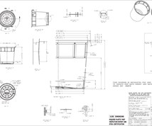
Despite the claims made about paperless mold design, all toolmakers still require some drawings for their manufacturing, inspection and assembly departments. However, software suppliers have made considerable steps to automate the process for creating drawings. For example, the new drawing production process within some CAD/CAM software can generate automatically the General Assembly and all of the component drawings required for manufacturing and inspection.
With this high degree of automation, the time needed to produce a complete set of drawings for even a complex mold should be no longer than a day. This compares with the two or three weeks that are typically needed with traditional drawing methods. All dimensions are displayed on the drawings as tables of parameters as well. This makes it much easier and quicker to program 2-D machining operations than the more traditional drawing layout with dimensions displayed all around the drawing.
Conclusions
With today’s demands for faster and faster new product development, mold designers are under greater pressure than ever to complete their work in the shortest time possible. A range of software is available to help them both complete the design and generate the necessary documentation. Companies need to invest in this technology to shorten their leadtimes and remain competitive.
RELATED CONTENT
-
Plastic Prototypes Using Silicone Rubber Molds
How-to, step-by-step instructions that take you from making the master pattern to making the mold and casting the plastic parts.
-
A Different Approach to Mold Venting
Alternative venting valves can help overcome standard mold venting limitations and improve mold performance.
-
New Innovations in Mold Design, Milling Cutters, 3D Scanning
MoldMaking Technology compiles a number of digital-only products from the past month, including mold design software, laser metrology 3D scanners, milling cutters and more.


