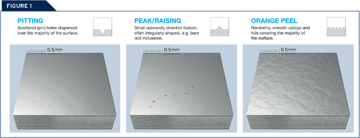
Figure 1. Pitting, peak/raising and orange peel are examples of common polishing defects. Photo Credit, all images: Uddeholm USA
The reasons for a high-gloss finish in plastic molding vary. Some examples include extreme transparency of the molded part, reduced localized corrosion or highly crack-sensitive tooling (due to design or operational stresses). Then there is the impact of mold surface finish on injection molding productivity, as the release forces of the plastic part from the mold steel surface depend upon the polymer’s adhesion properties. Remember that improved smoothness may lead to higher release forces, and, eventually, to a sticking phenomenon, which you can partly overcome with the appropriate tool steel choice and preparation strategy. Achieving a surface with a mirror finish requires several grinding, paper and diamond polishing steps, which you must perform in a clean workplace with the proper tools.
Polishing is a critical step when it comes to the manufacturing of high-quality inserts for plastic molding. Some of the most common defects include pitting, raised defects and orange peel. Pitting refers to scatter pin holes dispersed over most of the material’s surface, creating depressions. Raised defects are small, outwardly directed features that are often irregular in shape. Orange peel appears as hills and valleys covering the surface (see Figure 1).
Featured Content
Let’s break down some key challenges and considerations for achieving the best mold finish.
The Steel Factor
Your steel choice does impact part defects. For example, microcleanliness and microstructure strongly contribute to pitting, as polishing removes the softer matrix around an inclusion or carbide, resulting in peaks. Then, as polishing continues, the peaks are torn from the surface, yielding pits and needle marks (see Figure 2).
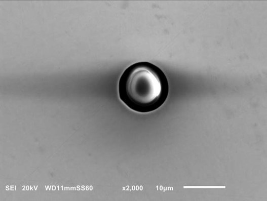
Figure 2. Polishing removes the softer matrix around an inclusion or carbide, resulting in peaks as seen in this image of an inclusion oxide.
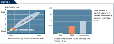
When projects demand high-quality surface finishes, use electro slag refined/remelted (ESR) grades and powder metallurgy (PM) steels, which have high cleanliness and whose carbides are smaller and rounder compared to conventionally produced steel (see Figure 3).
The hardness of the matrix also influences part defects. The higher the hardness, the lower the risk of encountering issues. For example, steel at a lower hardness (<45 HRC) is more prone to orange peel, so the polishing technique becomes very important. Orange peel can worsen with segregation or small differences in alloying content, leading to softer and harder layers in the matrix. Figure 4 shows a hardness profile for a P20-type material and the segregation causing significant variations in hardness (>100MHv0.2).
Surface Preparation and Polishing Techniques
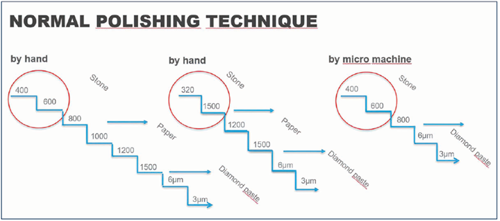
Problems can arise even when you use a high-quality steel grade, so check the polishing sequence. Surface finish before polishing plays an important role. For example, polishing on too rough a surface is one of the most common mistakes. It is recommended to begin stoning on a surface roughness of Ra/Rz = 0.5/5 µm. Then, to avoid pitting and orange peel, spend more time on the rougher stages and less time on the final stages.
Another mistake is over-polishing, which is polishing too long and often in combination with too much pressure. Instead, it would help if you used large polishing tools, since smaller tools tend to enhance variations in the steel that yield orange peel, pitting and peaks. The same goes for the hardness of the carriers. Harder carriers are preferred over softer ones since the latter removes more matrix in softer areas.
Figure 4. The microstructure on the left shows banding and segregation with its hardness profile on the right.
Poor choice of polishing consumables like stone, paper and diamond paste can also cause problems. Silicon carbide stones and a high concentration of diamonds in the paste provide shorter polishing time and finer surface finishes.
The environment also plays an important role when polishing, so polish in a separate toolroom to avoid corrosion caused by high humidity, dirt in the air landing in a cavity and scratch marks.
Corrosion and EDM
Pitting is also the result of corrosion, which occurs due to high humidity or using water during cleaning. Pitting may also be the result of electrolysis corrosion after wire EDM. You will typically experience this result directly after the EDM operation. However, it depends on the depth of the corrosion attack.
Furthermore, pay extra attention to how the EDM layer is removed. A typical EDM layer consists of a remelted and rehardened surface layer with many peaks and valleys. If the entire heat-affected zone is not entirely removed, the residues from the layer (usually the valleys) will appear as pitting in the surface.
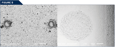
Arcing during EDM is also common, which causes craters that are deeper than the surrounding valleys. It is difficult to judge the reason for these pits with the naked eye or at low magnification, but a higher magnification reveals a surface that has been remelted . Use special polishing stones to remove the EDM layer properly (see Figure 5).
Solving the Problems
Immediately cease polishing when a defect appears, or you will worsen the problem. The best plan of action is as follows:
- Re-stone the surface, repeat polishing with lower pressure and check the carriers used.
- Perform in a cleanroom that controls the temperature, humidity and particles in the air.
- Use a face mask to avoid the risk of saliva contaminating the surface.
- Clean hands, clothes and tools carefully between each step.
- Spend more time on the coarser steps.
- Use hard carriers instead of softer ones.
Material Choice and Other Variables
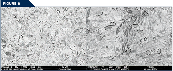
Your mold material choice has its own impact on the final surface finish. For example, a martensitic stainless grade1 was developed to meet the high requirements of a high-gloss surface finish. This material type is considerably easier to polish than Werkstoff Number (W.Nr) 1.2083/AISI 420 steel types. This material’s most important feature is the microstructure, as the carbides are fewer and smaller compared to W.Nr 1.2083/AISI 420 (see Figure 6).
Figure 6. Comparison of carbide size and distribution: Uddeholm Tyrax ESR (left) W.nr: 1.2083 ESR (right).
An additional benefit is that this martensitic stainless grade can reach a hardness level of 58-60 HRC, making the material easier to polish. The alloying composition of the carbides has been adjusted, which results in improved wear resistance compared to W.Nr 1.2083/AISI 420. Optimized carbide distribution and alloying design also improve the mechanical properties, yielding less risk of crack initiation and crack propagation compared to other martensitic stainless grades.
Heat treatment is another critical polishing factor, as it impacts the surface. For example, decarburization and quench speed impact the microstructure. Also, the method used to machine the surface might affect the final result. For instance, if you used EDM, it is essential to remove the recast layer and the affected layer underneath. To avoid corrosion that will cause defects, carefully dry the workpiece between every machining operation and ensure the wire EDM is in good condition.
Achieving a high-gloss surface finish requires the proper tool steel with high cleanliness and a small, even carbide distribution. Then, when polishing, carefully select the environment, starting surface, pressure, time and consumables.
References
1 Uddeholm Tyrax ESR from Uddeholm AB.
RELATED CONTENT
-
7 Key Advantages of Hot Runner Systems
While both hot runner and cold runner systems have their benefits, for design flexibility as well as reduced cycle times and costs, hot runner systems will probably be the better choice.
-
Selecting a Carbide End Mill for Aluminum Applications
Specific geometries and characteristics of a carbide end mill are required for efficient machining of aluminum.
-
Texturing Molds for Thermoplastics: Factors for Success
Factors to consider when selecting a texture or grain for a thermoplastic mold or die.
.jpg;maxWidth=970;quality=90)

